Cognex Camera Wiring Diagram
Download product information, installation & operation manuals, technical specifications, and more. Pin wire color signal 1 white camera input power ground.
Cognex Checker 101 80700045 Rev E, Transamerican Equipment Company
Cal output line on the camera, and to provide power to the camera (if poe is not used).
Cognex camera wiring diagram. Wiring diagram cx vision system. Configuring the camera for modbus tcp slave operation: Setting up a part in feedwarecx.
Cognex standard i/o and ethernet cables. (check the compatible cable in the following. Gige vision and camera link cameras are available in both area scan and line scan formats to address a wide variety of applications.
Notice lens thread length is. Label on bag cognex pn w/barcode braid wire 38 awg cable assembly type iec test and qualification vendor connector compatibility category 5e performance wiring validation functionality x x emi mechanical dimensions workmanship packaging and labelling verification flex life(bending test) business unit review/approval hi pot testing ip67 cognex x. Wiring diagram between plc and cognex camera.
Using the wiring diagram in the camera's installation manual, wire the camera to 24 v and ground (also ground. Download product information, installation & operation manuals, technical specifications, and more. In this camera, there are two personalities in the option, persence and.
Camera that will be connected to the single camera connection module. The electrical connection or wiring diagram of cognex vision camera is as show in figure 3. Access documentation related to cognex dataman 260.
A link to this download will be sent to the recipient specified below. Contact your cognex sales representative for information on cables that are compatible with your cognex cameras. Whether you choose a cognex industrial camera (cic) or third party camera, seamless.
Make sure that the cable is secured tightly in the cable gland. You can use additional switches, bridges, and routers to connect. Pc vision wiring guide april 2014 cognex 1.
With its ability to acquire and process exceptionally detailed images, the 12 megapixel (mp) 9912 delivers high accuracy part location, measurement, and inspection over a large area—even when mounted at longer distances. Pins 1 and 2 are connected inside the camera. The following diagram labels the pins on the connector:
It is known that the lvds receivers on. 2) connect the power cable of a breakout cable and the terminal compatible with the power supply. Cognex visionview has 4 poe ports and 1 lan port:
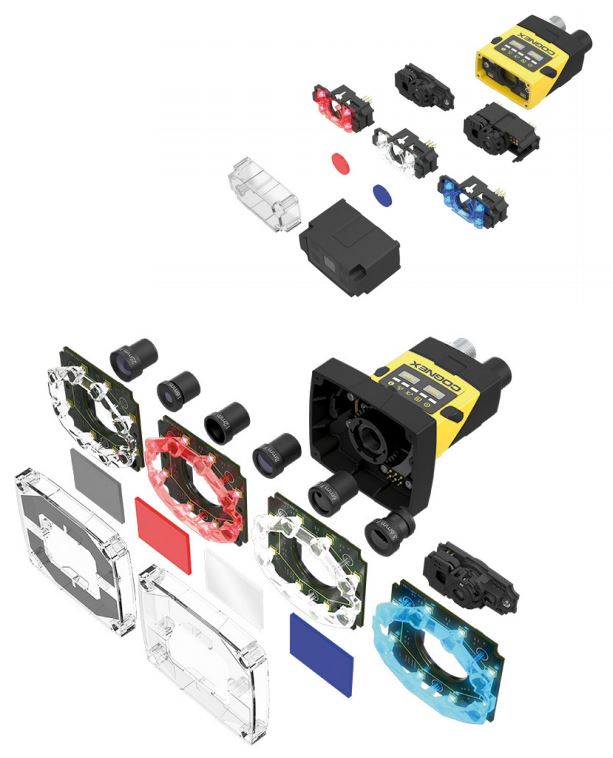
Cognex Vision Sensors InSight 2000 and InSight 2000 Mini Acrovision Blog Acrovision

Phone Camera Circuit Diagram Wiring View and Schematics Diagram
Cognex Cognex 3D Displacement Sensors (DS1000 Series)

Mobile Camera Circuit Diagram Wiring View and Schematics Diagram
Foveal Systems FM2_2a Mount for Cognex 7000 Camera

Cognex Unveils 3DA1000 Item Detection System News
Foveal Systems FM2_2a Mount for Cognex 7000 Camera

ebay id fluke.l store blog 出售 ZYGO 7702 laser heard 激光头13580417781

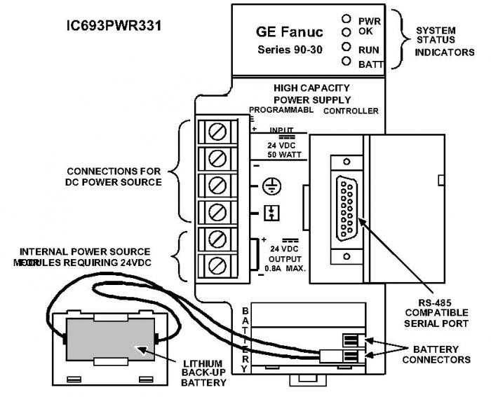
IC693PWR331 GE Fanuc Qty 5 New In Stock Buy Online PDF Supply
Final Design Fin Can Section Subassembly Ben Staal's Rocketry
Cognex 80057581 J In Sight I/O Expansion Module Scanner Camera Wired In Box Bullseye

Phone Camera Circuit Diagram Wiring View and Schematics Diagram
Cognex 80057581 J In Sight I/O Expansion Module Scanner Camera Wired In Box Bullseye

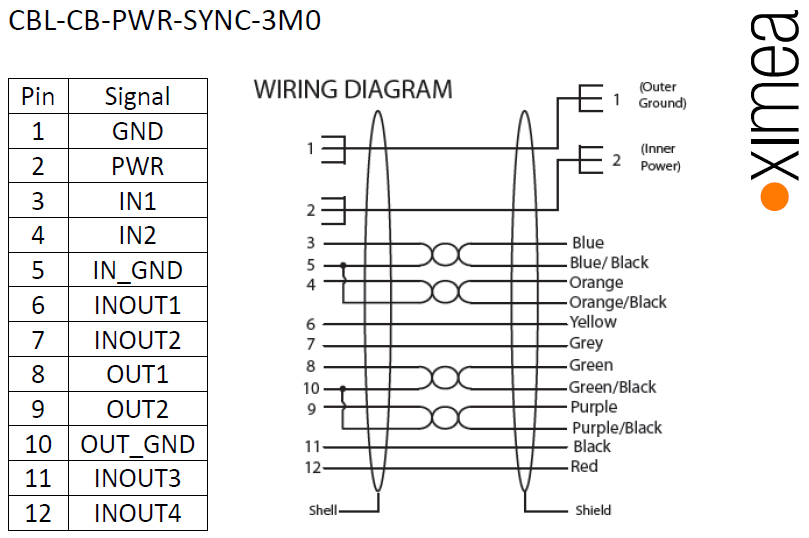
PCI Express camera xiB xiB ximea support

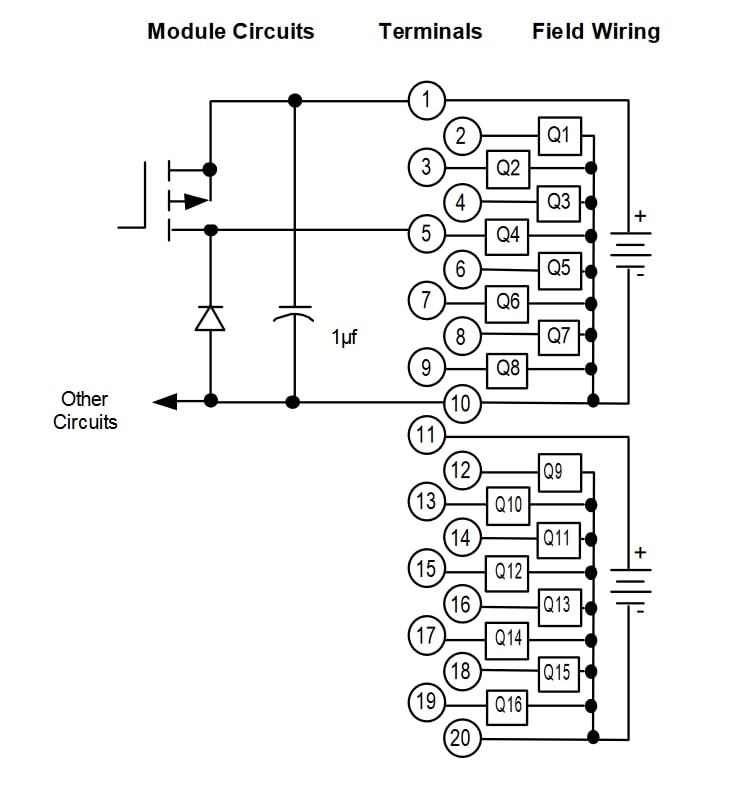
IC694MDL740 GE Fanuc Qty 5 New In Stock Buy Online PDF Supply

Sensores de visión InSight 2000 Cognex

Cognex vision sensorview HVS System

